
Technical Data
BLAST stands for Biliquid Launch and Space Technology and is our team’s current main project. In its course, we are aiming to develop a sounding rocket which combines several innovative and complex technologies.

Recovery
The BLAST recovery system will be a single chute system. In order to mimic the two-stage behaviour of the traditional drogue-main-combination, we are currently developing a self-made active skirt reefed main parachute. By choosing this approach, we hope to drastically decrease total system mass and volume.
We are planning on using a reefing line to control the opening of the parachute. While this will allow us to move the actuators away from the parachute skirt into the rocket’s hull, it also creates two parallel lines, which have to swivel around the same axis. To avoid any entanglement of the two lines, we are designing a custom hollow swivel which will allow the reefing line to pass through the main line swivel.
Since there is relatively little research in active parachute reefing systems at small scales, we will perform tests to determine the parachute type best suited for our configuration. In early wind tunnel testing, we have already found the traditional round canopy parachute to be very unstable in comparison to other parachute shapes.
Avionics
For Project BLAST, the avionics team has set ambitious goals. We are developing a redundant flight computer capable of determining the rocket’s flight state, processing data from a wide range of onboard sensors, and maintaining a robust communication link with the ground station throughout the entire mission.
Redundancy and System Architecture
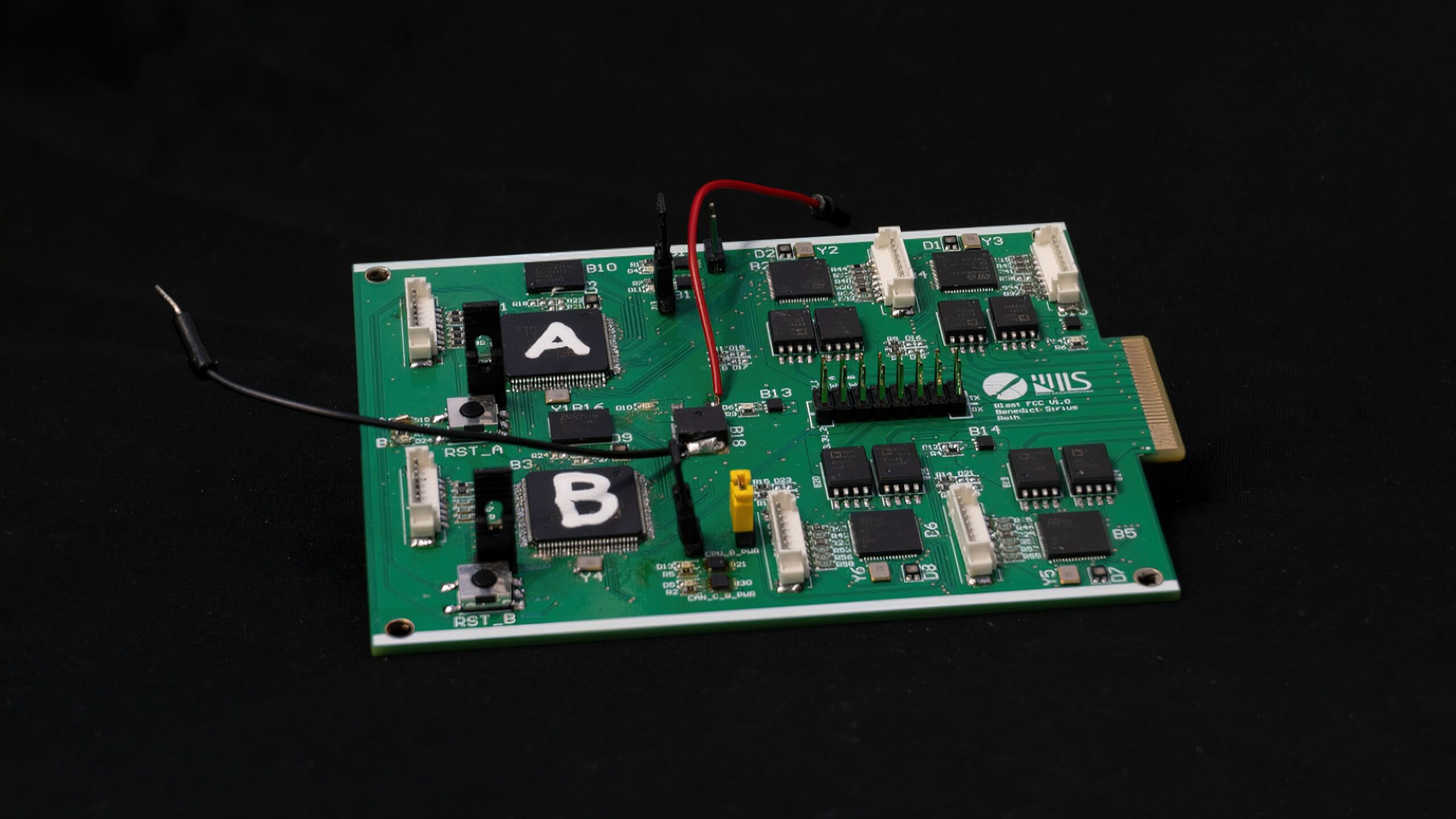
Reliability is paramount for avionics. The flight computer is built as a dual-duplex system, featuring two independent computation units, each equipped with two processors. All four processors run flight-state estimation algorithms in parallel, continuously exchanging and validating their results. If one processor produces inconsistent data, the system automatically detects and isolates the fault — ensuring that no single-point failure can jeopardize the mission.
Sensor Reliability
Accurate flight-state estimation depends on trustworthy sensor input. To enhance robustness, critical sensors — including IMUs, barometric sensors, and GNSS receivers — are integrated redundantly. This allows the system to tolerate individual sensor failures or implausible readings while still maintaining reliable operation.
Propellant Handling and Ground Operations
During fueling and pre-launch procedures, monitoring the rocket’s pressurized systems is essential. Pressure transducers and temperature sensors distributed throughout the rocket feed data via sensor nodes connected over a CAN bus to the main flight computer.
While the rocket is secured on the launch rail, this data is transmitted to the ground station through a tethered connection. For the flight phase, communication seamlessly transitions to a custom-designed RF downlink, which continuously transmits telemetry to the ground station. Additionally we plan to develop and testour own antennas to ensure a reliable and high-performance data link throughout ascent and recovery.
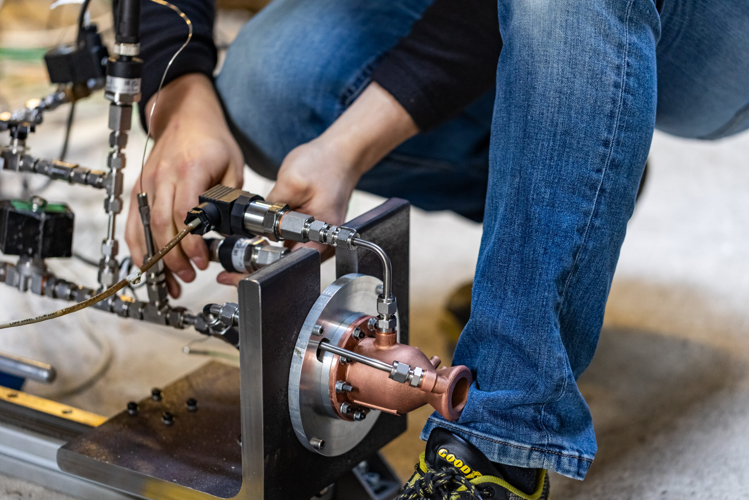
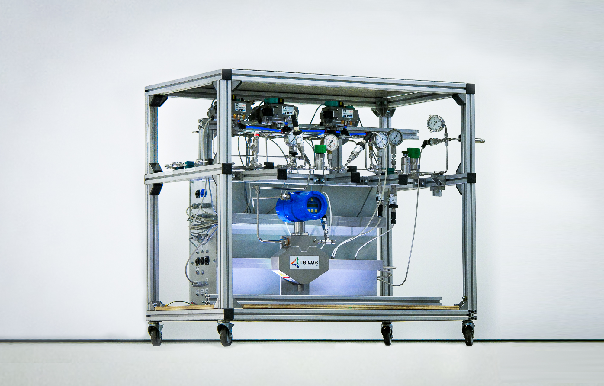
Fluid System
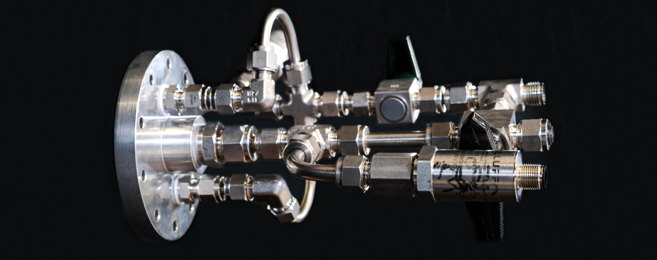
Our fluid system is marked by cutting-edge features, notably the use of a 3D-printed main valve, ensuring weight reduction and a more compact design. Rigorous testing procedures are implemented to guarantee system reliability, validating its performance under diverse flight conditions.
Key achievements include the development of robust depressurization mechanisms, such as self-designed pressure relief and vent valves, ensuring secure and controlled tank evacuation. Collaboration with Ground Support Equipment (GSE) specialists ensures a smooth tanking process, optimizing the integration of the fluid system with ground support infrastructure.
The team’s focus on a highly integrated system prioritizes optimization of weight and volume, resulting in a compact and efficient rocket design. Constant pressure regulation is maintained through mechanical pressure reduction, thus adapting to changing conditions during flight.
Structure
All components will be optimally designed to the flight profile of our rocket and will be verified through mechanical, thermal, and aerodynamic simulations as well as rigorous testing, including load cycle and vibration tests.
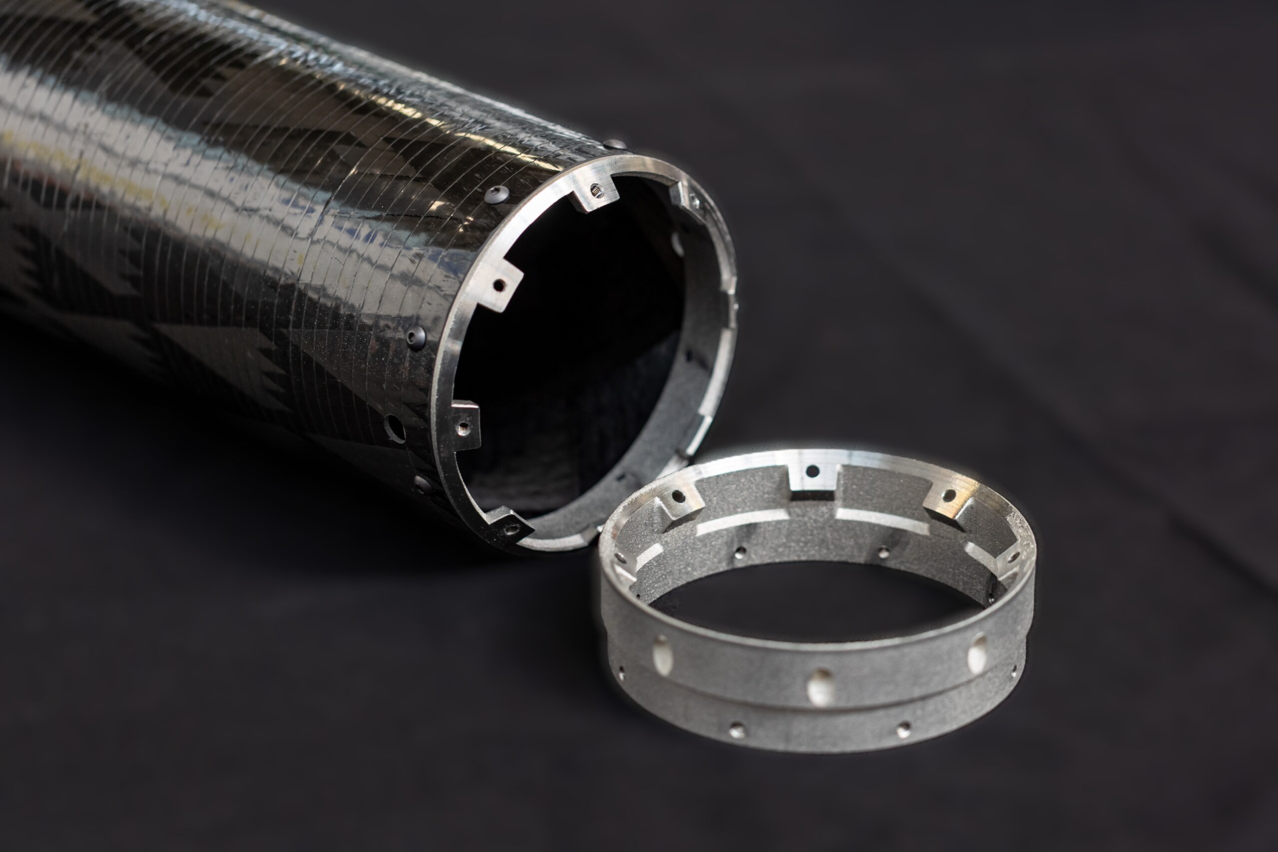
To push the light-weight engineering of our rocket to its limits, we will also be using RADAX connectors to join the various parts of our rocket together as this compact connection allows us to reduce the total length of the rocket. While RADAX connectors are conventionally made of metal, one of our members has designed a CFRP RADAX connector for his bachelor’s thesis. Implementing this change of materials will lead to massive overall weight savings.
We are currently developing a linerless CFRP oxidizer tank using an in-house developed epoxy resin matrix which does not react with nitrous oxide. On top of the cheaper manufacturing cost, this Type V pressure vessel will have significant weight reduction compared to an aluminium-liner tank, which was used in our previous rocket and is currently the state-of-the-art in oxidiser tank development.
We have already successfully developed a linerless CFRP fuel tank, which has been pressurized to 120 bar. It will soon be tested to destruction in order to determine its limits. The filament winding machine used to make these pressure vessels as well as the rocket’s exterior hull has been built and perfected by HyEnD’s members and is powered by TANIQWind. TANIQ’s substantial support has enabled HyEnD to take the next steps in fiber-wound lightweight design, compared to our N2ORTH rockets. Owing to the TANIQWind software, reliably reproducible pressure vessels and hull structures can be produced, which is invaluable for research and development on HyEnD’s state-of-the-art lightweight structures.

Further innovations that we wish to realize in the course of this project include retractable rail buttons that will improve the aerodynamics of the rocket’s flight, an integral tank design as well as manufacturing our engine mount from light-weight composite materials.
Propulsion
The BLAST rockets are propelled by liquid engines using nitrous oxide as oxidizer and ethanol as fuel. How much thrust are we aiming for? As much as our test sites will allow. Said test sites are the Materials Testing Institute (MPA) at the University of Stuttgart, where we have an entirely self-developed and self-built test bench, and the test bench at the engine test site M11 at DLR Lampoldshausen. If you are interested in having a closer look at our testing setup and about how a test day usually looks like, have a look at the YouTube video below!

In order to develop a viable engine, we first tested several injector types with water, then with the respective propellants. Following this, we conducted hot-fire tests on a sub-scale engine with a thrust of 550 N. The same procedure was followed for the regeneratively cooled engines. In the end, we decided on an impingement injector.
Until now, we have successfully fired 550 N engines and 1 kN engines in different configurations. With a chamber pressure of 60 bar, our engines are rather unique in the world of student rocketry.
Battleship Engines
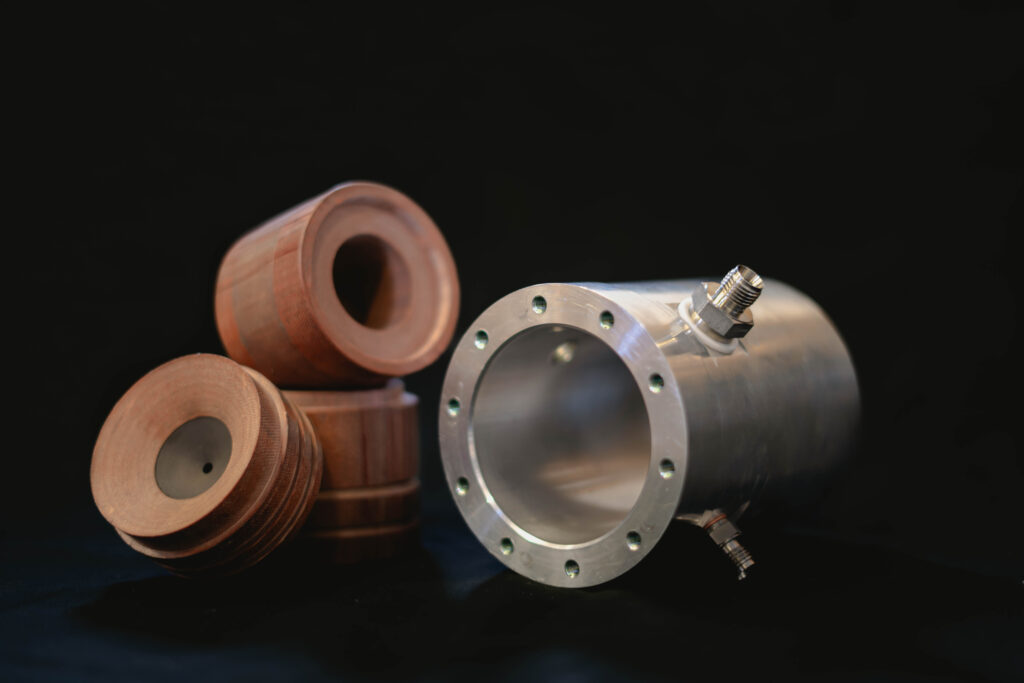
We like to describe un-optimized and over-dimensioned engines we use for the initial characterization of a new engine as a battleship engine. This engine type minimizes the risk during engine tests even if unexpected events such as pressure and thrust spikes were to occur.
Our battleship engines consist of an aluminum housing for the combustion chamber and nozzle, which is made from phenolic paper. As the engine is fired, the top layer of the phenolic paper will gradually ablate, thus cooling the engine. This is called ablative cooling. A graphite throat enables us to fire the same engine multiple times without too much variation in the combustion chamber’s geometry.
Regeneratively Cooled Engines
We don’t only like to build rocket engines, we also like to do science. As such, we decided we wanted to try our hand at regeneratively cooled rocket engines. A staple of modern-day rocketry, one of the propellants is led through cooling channels in the wall of the combustion chamber in order to cool the material and prevent it from melting. Both propellants are then injected into the combustion chamber. Regenerative cooling allows for rocket engines to be fired in perpetuity, or at least until the propellants run out.
Regeneratively cooled combustion chambers are usually made from metal due to the required thermal properties of the material. We chose to additively manufacture the regeneratively cooled chambers. Most of the our combustion chambers are provided by the Materials Testing Institute (MPA) at the University of Stuttgart and TRUMPF. To this day, we have successfully test-fired 550 N regeneratively cooled engines of varying materials.
In 2025, we published a paper for EUCASS about the research we did on additively manufactured liquid rocket engines, which you can read here.
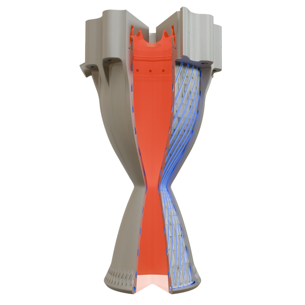
Render of a regeneratively cooled engine with visible cooling channels (blue), with the inside of the combustion chamber (red).
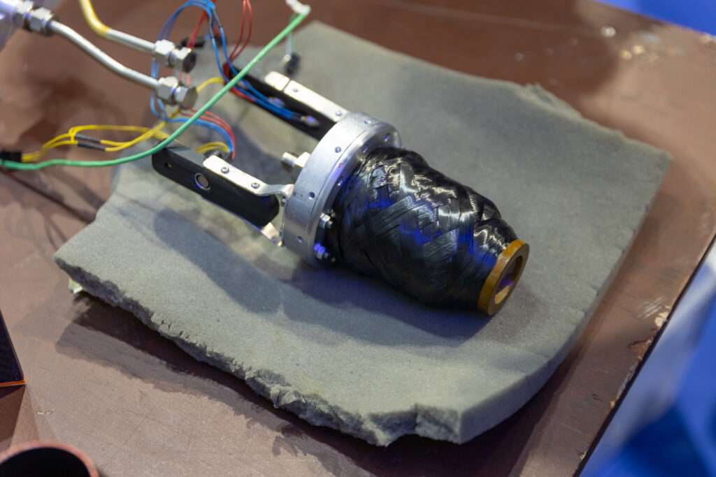
Carbon Fiber Overwrapped Engines
One of the deciding factors of how high your rocket flies is weight. We chose to weight-optimize the ablatively cooled combustion chamber of the battleship engines by foregoing the aluminum casing, instead opting for a fiber-overwrapped design. The only metal in this design is for the aluminum flange which connects the engine to the injector and the propellant manifold. This design was only possible thanks to the TANIQWind software we use on our filament winding machine.
We recently flew a 1 kN variant of the carbon fiber overwrapped engine at EuRoC 2025, check it out below!
Ground Support
At HyEnD, we are not just building rockets, we are also launching them. This brings up the ground support equipment (GSE) for the upcoming BLAST project. Often the unsung hero, the GSE is critical in ensuring that each rocket launch is executed flawlessly. Without this essential subsystem, our rockets would remain on the ground. The GSE is an interdisciplinary subsystem, incorporating thermodynamics, fluid mechanics, electronics, and more.
The GSE includes the fueling system and the launch rail. These systems are developed and designed to accommodate the requirements of both the demonstrator rockets and the full-scale launcher, and will also be used for the launch of our N2ORTH 3 rocket. It is necessary for these systems to be safe, reliable and transportable. The environmental conditions of the launch site also have to be taken into account.
The fueling system is comprised of two compartments, a fluid compartment and an electronics compartment, which are interconnected. It is responsible for fueling the rocket’s tanks with nitrous oxide, ethanol, and helium, respectively. The fueling process is continuously monitored with pressure and mass flow sensors, and is regulated with pneumatic valves and pressure regulators. The control cabinet contains the electronics necessary for reading the sensor output and controlling said valves and pressure regulators.
As we are not allowed to employ thrust vectoring in our rockets, they need to be guided by the launch rail until they reach the velocity necessary for a stable ascent. In this case, the rail is 12 meters long and secured to the ground by means of ground anchors. The rail also houses fueling arms, which connect the fueling system to the rocket, and are positioned on truss segments and aluminum extrusions which can be retracted automatically just before flight.
For safety reasons, it is necessary for said systems to be controlled remotely. In order to avoid radio interference, we have chosen to use fiber optic cable for fast and reliable communication.
Our GSE has been successfully tested during EuRoC 2025 and is ready for the next launch!
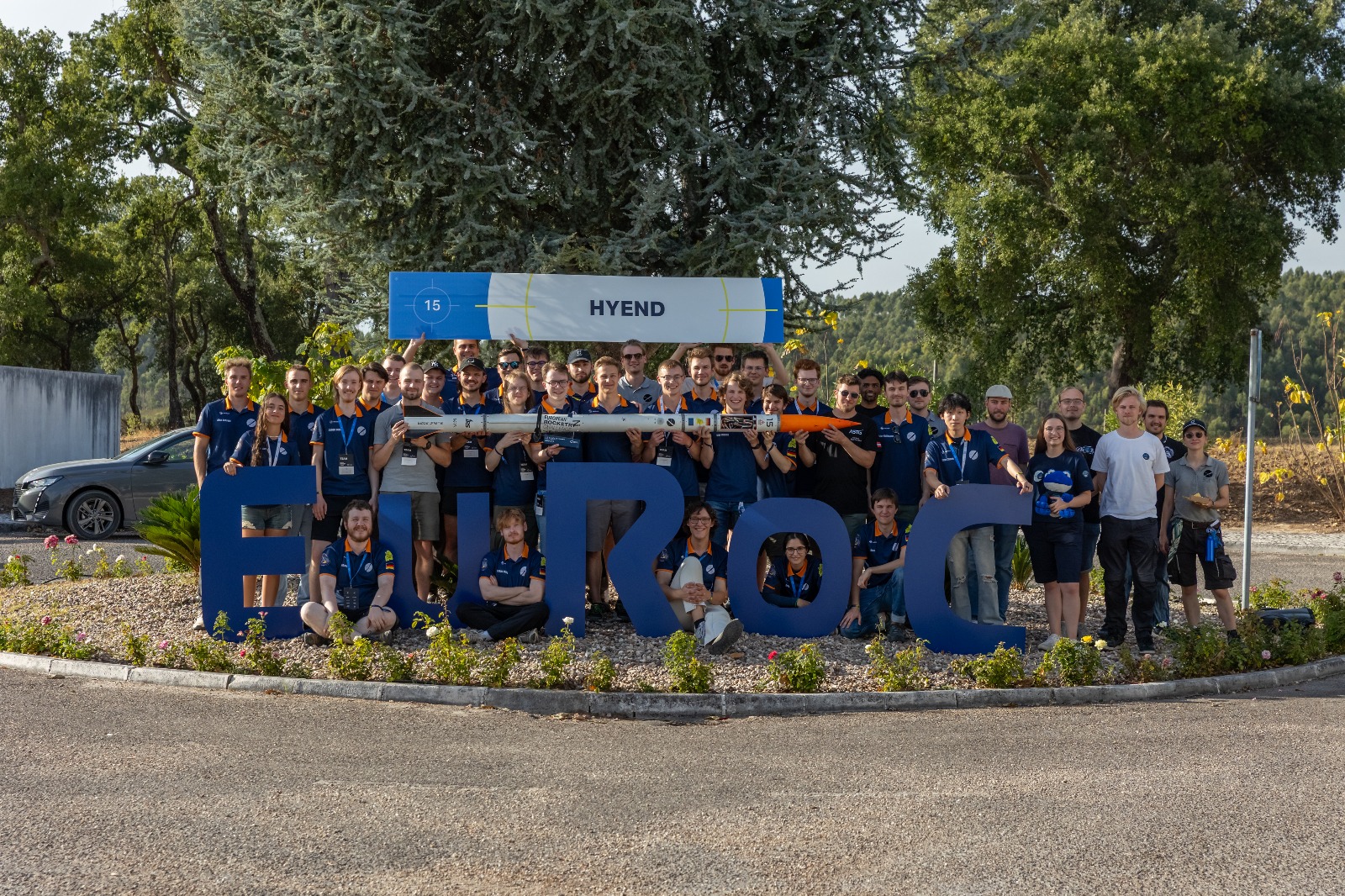
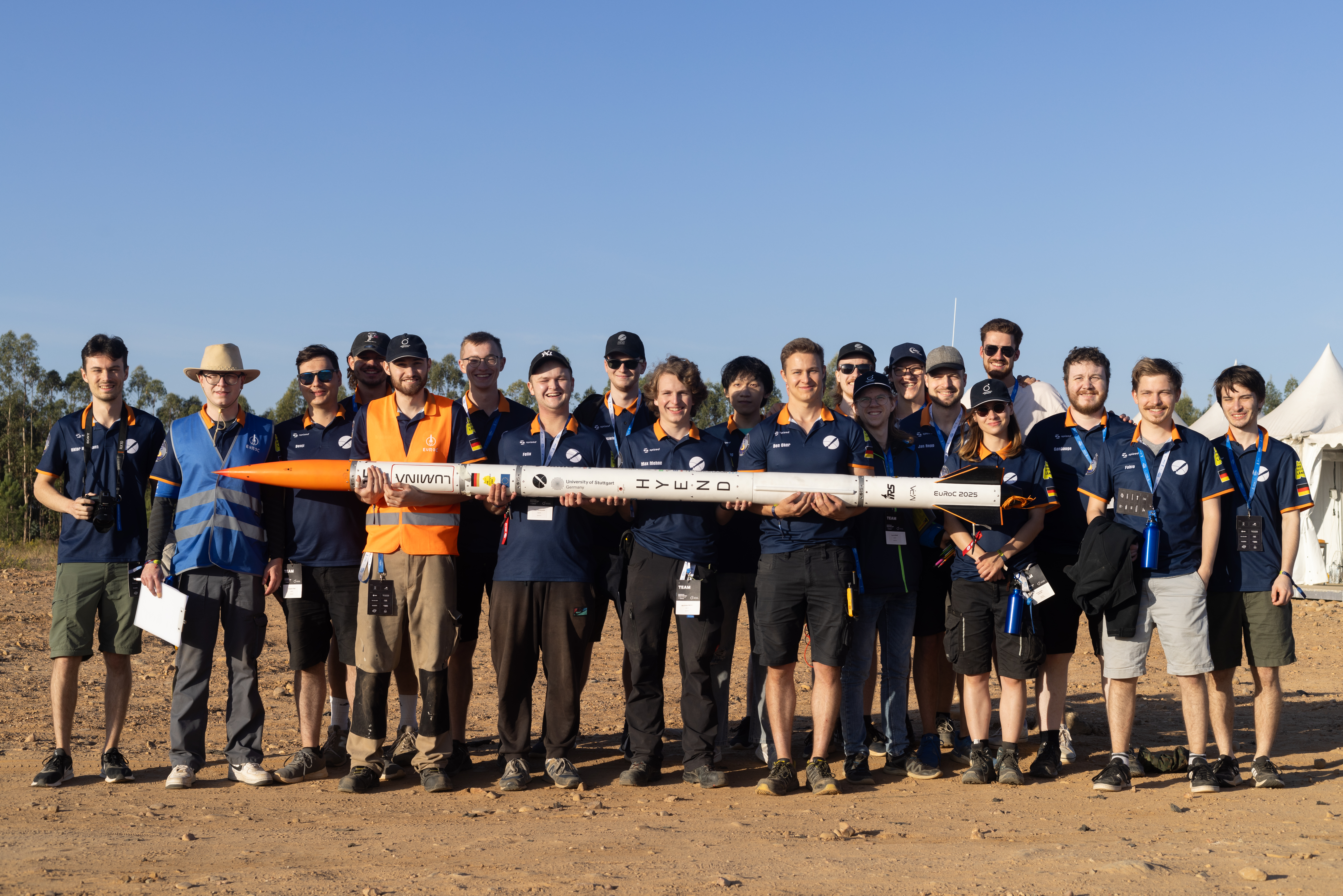
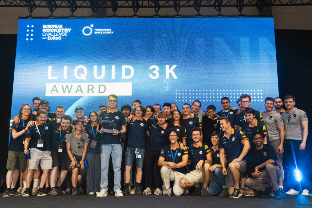
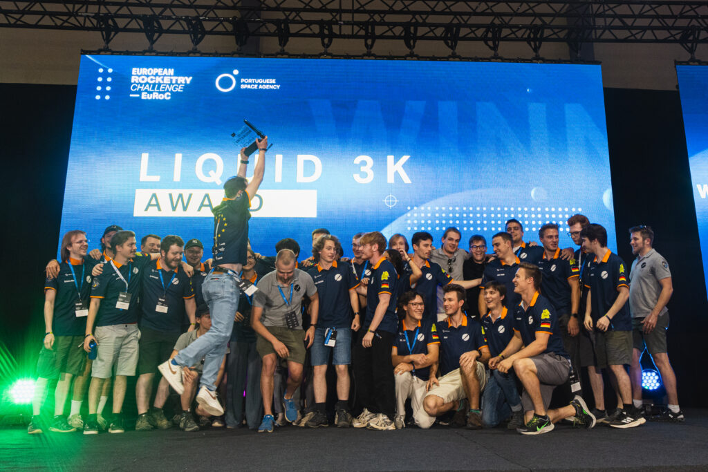
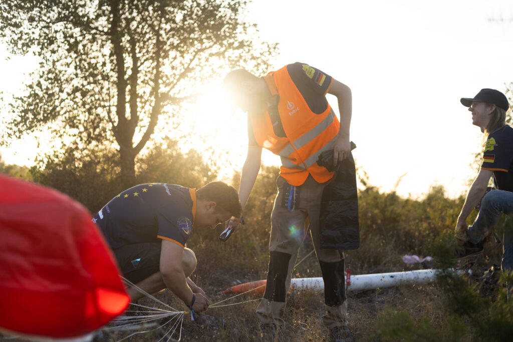
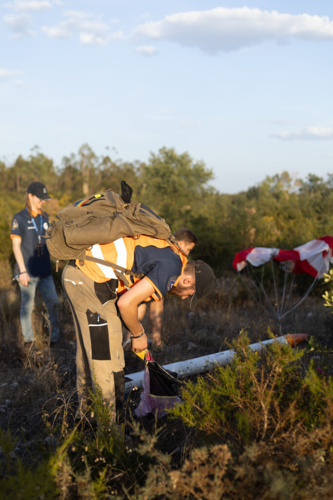
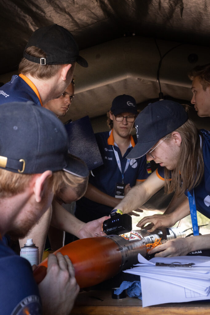
Lumina Launch Campaign – EuRoC 2025
Let’s put the thing y’all want to see most first: the launch video. This one’s a clip of the official EuRoC live stream on YouTube, our own videos with views from the onboard cameras to follow soon!
And the results of the launch? A nearly perfectly stable rocket, perfect recovery, and a close-to-exact 3 km altitude. Here’s a collection of pictures for you to enjoy! Exact data and further pictures coming soon!

Are you interested in sponsoring a world-record holding rocketry team? Then take a look at our sponsor presentation!