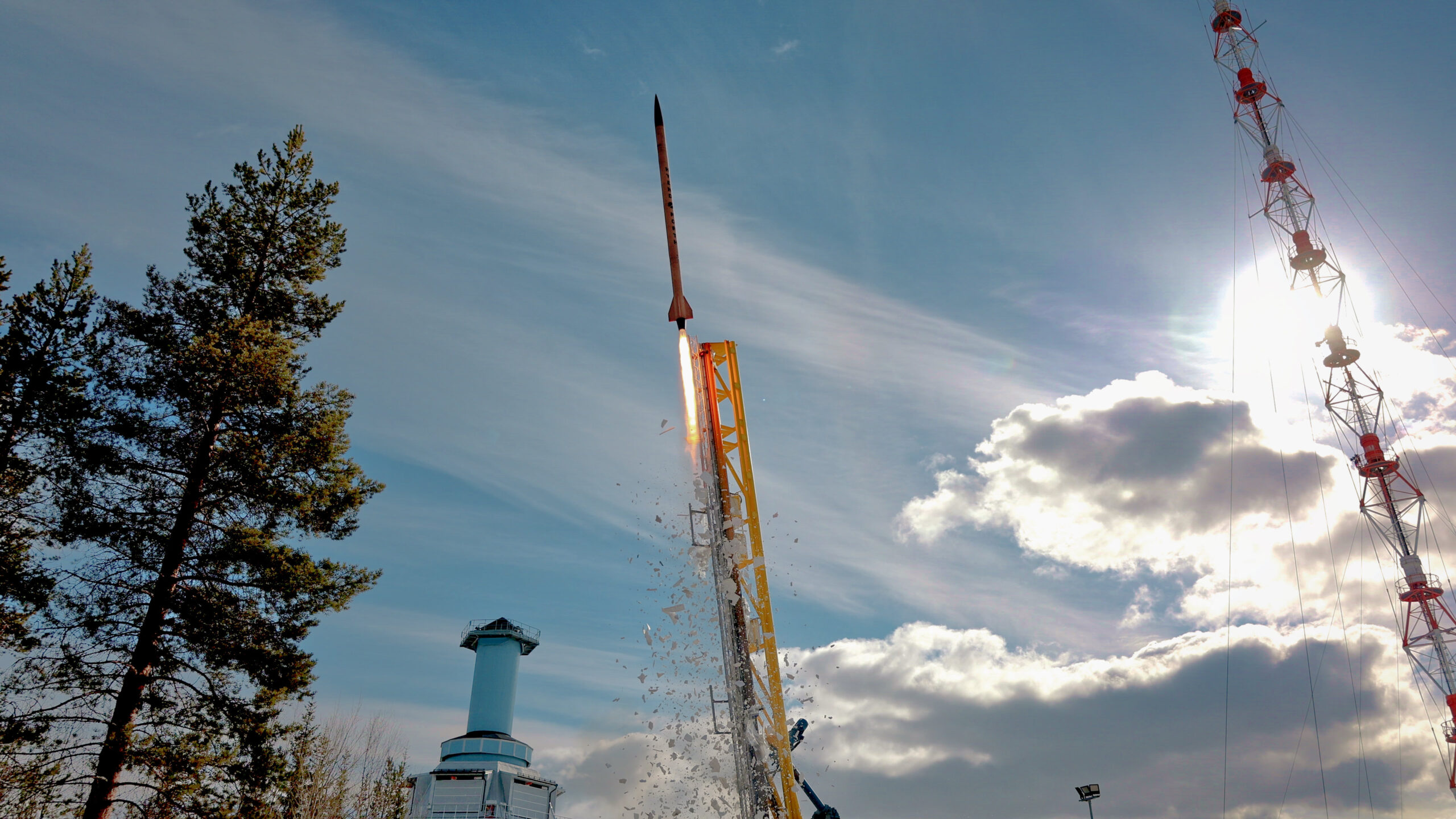

64 km Altitude: New Record for Student-built Hybrids
Pushing the Limits of Hybrid Propulsion
Learn more about the N2ORTH rockets and the technical details.
Watch the video and read the launch campaign reports.
Learn more about the DLR STERN Program.
Meet the people behind the rocket!
With N2ORTH, HyEnD has developed one of the most powerful and advanced student-built hybrid rockets in the world. On Tuesday, 18th April 2023 N2ORTH reached an altitude of 64 km. This almost doubled the previous altitude record for student-built hybrids, which we established in 2016 with the HEROS 3 rocket. The project is funded by HyEnD’s second participation in the DLR STERN Program.


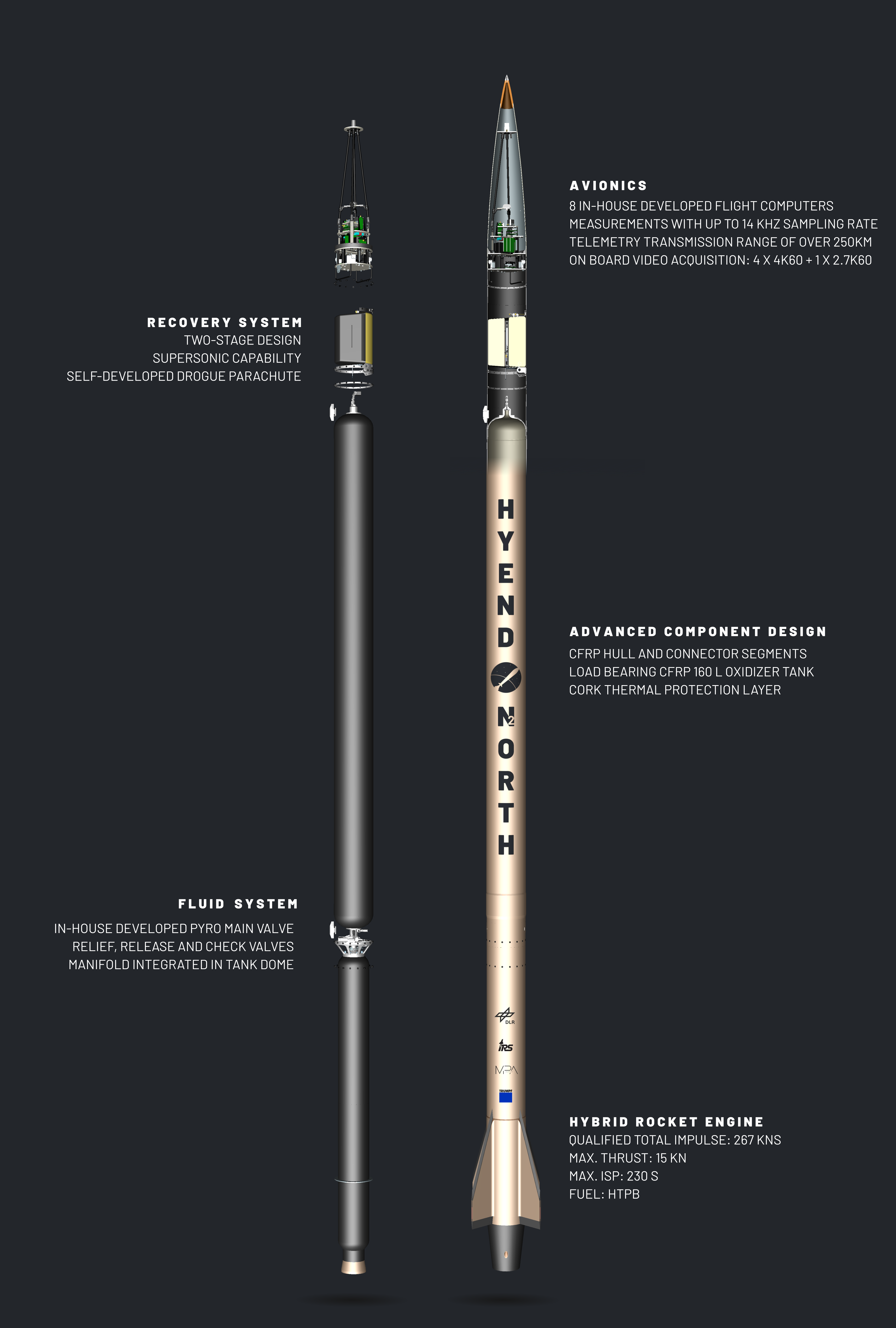
N2ORTH – Technical Overview
Learn more about our record breaking rocket
Propelled by its powerful HyLIGHT Hybrid Rocket Engine with up to 15 kN thrust, the first N2ORTH rocket has reached an altitude of 64 km. The rocket uses nitrous oxide and a new, in-house developed fuel. Innovative and lightweight structural elements are used. The composite oxidizer tank has no liner and is made using a new production process. Nitrous oxide compatibility is ensured by a polymeric coating. All valves and fluid systems are completely new developed with weight optimizations in mind. The two-stage recovery system for the whole rocket is designed for supersonic speeds. All components are extensively tested at appropriate test facilities to ensure a maximum of safety and reliability.
Why did HyEnD built two N₂ORTH rockets?
Since N₂ORTH is a new launch vehicle, we needed to make sure it performs as expected. That is why we limited the oxidizer mass and launcher elevation for the first launch. For the second launch, the oxidizer mass and launcher elevation were increased. Both N₂ORTH rockets feature the same component design with one exception: The first N₂ORTH rocket features an oxidizer tank with an aluminum liner. The oxidizer tank of the second N₂ORTH rocket is a liner-less Type V pressure vessel with a ETFE coating on the inside to ensure compatibility with nitrous oxide. This reduces the rocket mass by 7.7 kg. Originally, it was the plan to have two rockets with liner-less tanks, but that was not possible due to delays in the supply chain.
How was the technology tested in advance?
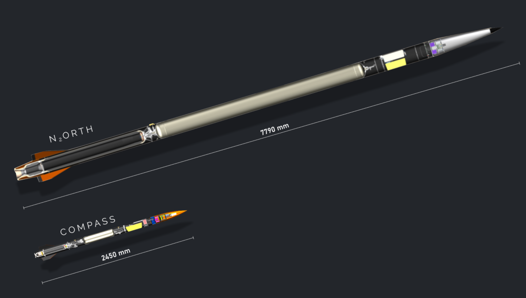
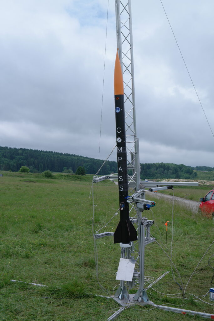
In order to test the new systems, a subscale demonstrator rocket called Compass was built and launched in advance. The launch of Compass took place on Friday, 25th June 2021 and demonstrated HyEnD’s capability of launching advanced hybrid rockets. All key elements of the design of N2ORTH are part of Compass as well.
What are the specifications of the rockets?
| Lift-off Thrust | 15,000 N |
| Nominal Thrust | 10,000 N |
| Length | 7.79 m |
| Diameter | 259 mm |
| Tank Volume | 160 L |
| Dry Mass | 69.2 kg / 76.9 kg* |
Scroll down to learn more about the different subsystems of N2ORTH. Every subsystem has its own dedicated team, which develops, builds, and tests the corresponding components. For the most part, the subsystems share the same working principle between N2ORTH and Compass.
Propulsion System
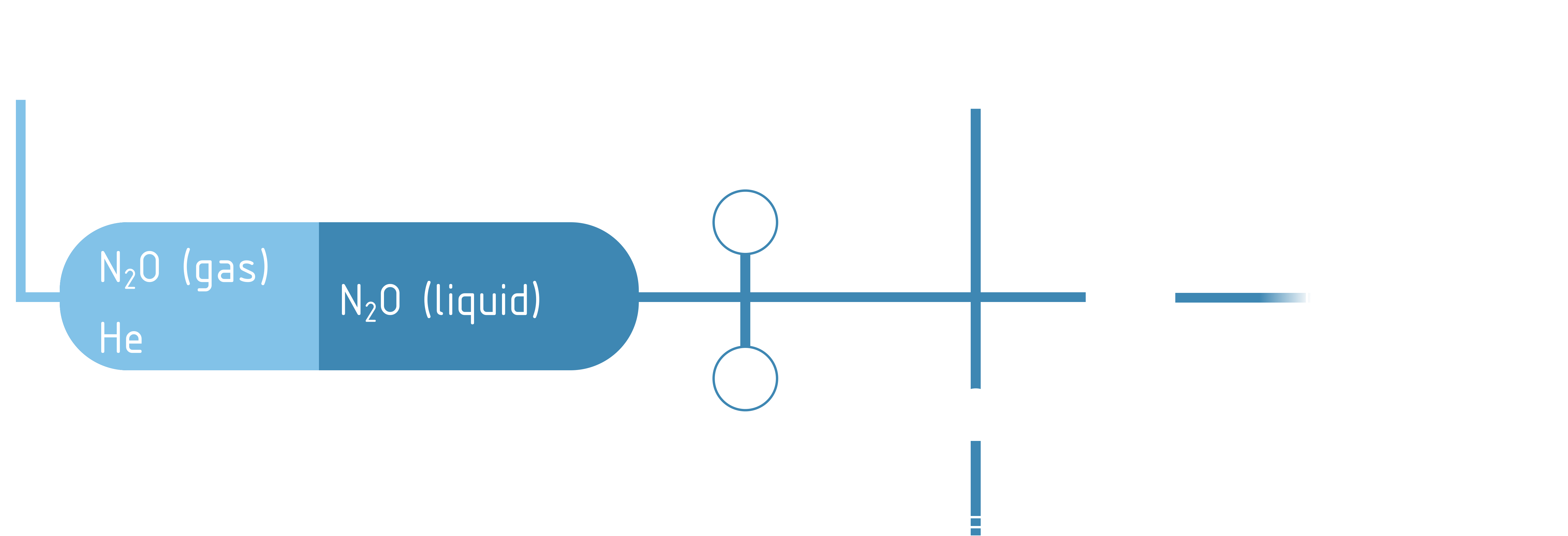
Both rockets, N2ORTH and Compass, feature a lightweight and efficient hybrid rocket engine with a CFRP combustion chamber hull. The propellants used are nitrous oxide (N2O) as oxidizer and a custom developed HTPB-based fuel. The propulsion system operates in blow down mode, meaning there is no active propellant feeding system. Instead, the self-pressurization capability of nitrous oxide is used and enhanced with additional helium, which is stored in the same tank. This principle is called helium supercharging and increases the lift off thrust and ensures a safe pressure difference between tank and combustion chamber.
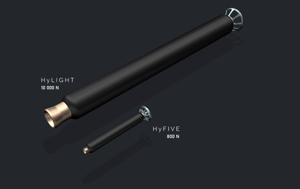
| HyFIVE Flight Engine | HyLIGHT Flight Engine | |
| Nominal Thrust | 800 N | 10,000 N |
| Maximum Thrust | 850 N | 15,000 N |
| CC Pressure (nominal) | 25 bar | 28 bar |
| Nozzle exit pressure (nominal) | 1 atm | 0.6 atm |
| Qualified Impulse | 4,200 Ns | 267,000 Ns |
| Specific Impulse (SL) | 211 s (@ 25 bar) | 224 s (@ 28 bar) |
| Fuel Mass | 900 g HTPB | 22 kg HTPB + 3 kg Film Cooling Ablator |
| Dry Mass | 950 g | 14.5 kg |
In-house Developed Fuel
The in-house developed HTPB based fuel is completely non-toxic during all production steps and castable at room temperature. The grains feature a single-port geometry. Both engines have demonstrated highly efficient combustion (>95% c* efficiency).

Non-toxic components of the fuel.
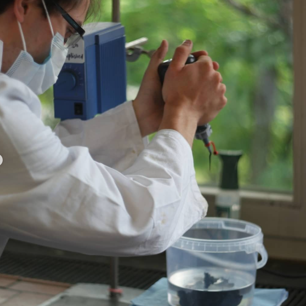
Safe and simple production.
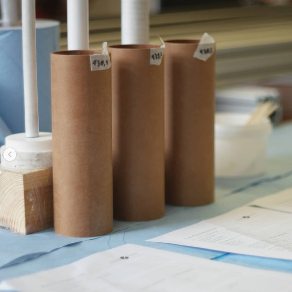
Fuel Grains for Fuel Evaluation
Lightweight Engine Design
For our project, we decided to use a filament-wound combustion chamber design. All casings are produced within our facilities with our new filament winding machine.
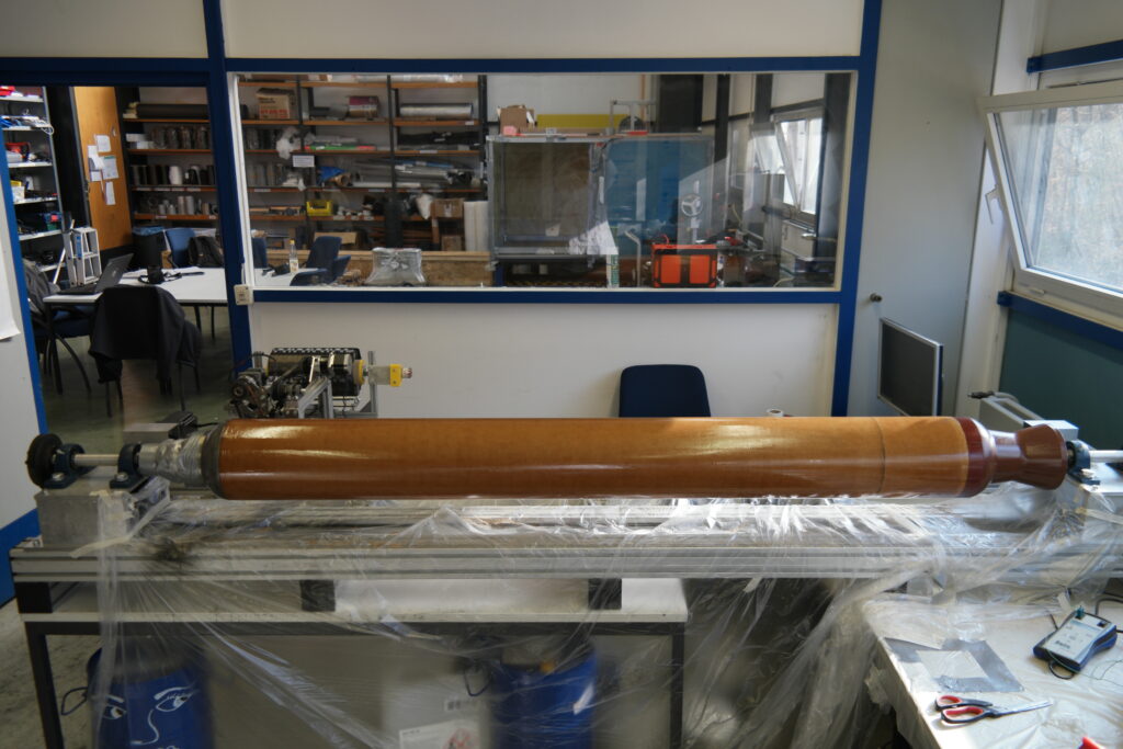
HyLIGTH engine on winding machine.
Filament-wound HyLIGHT engine.
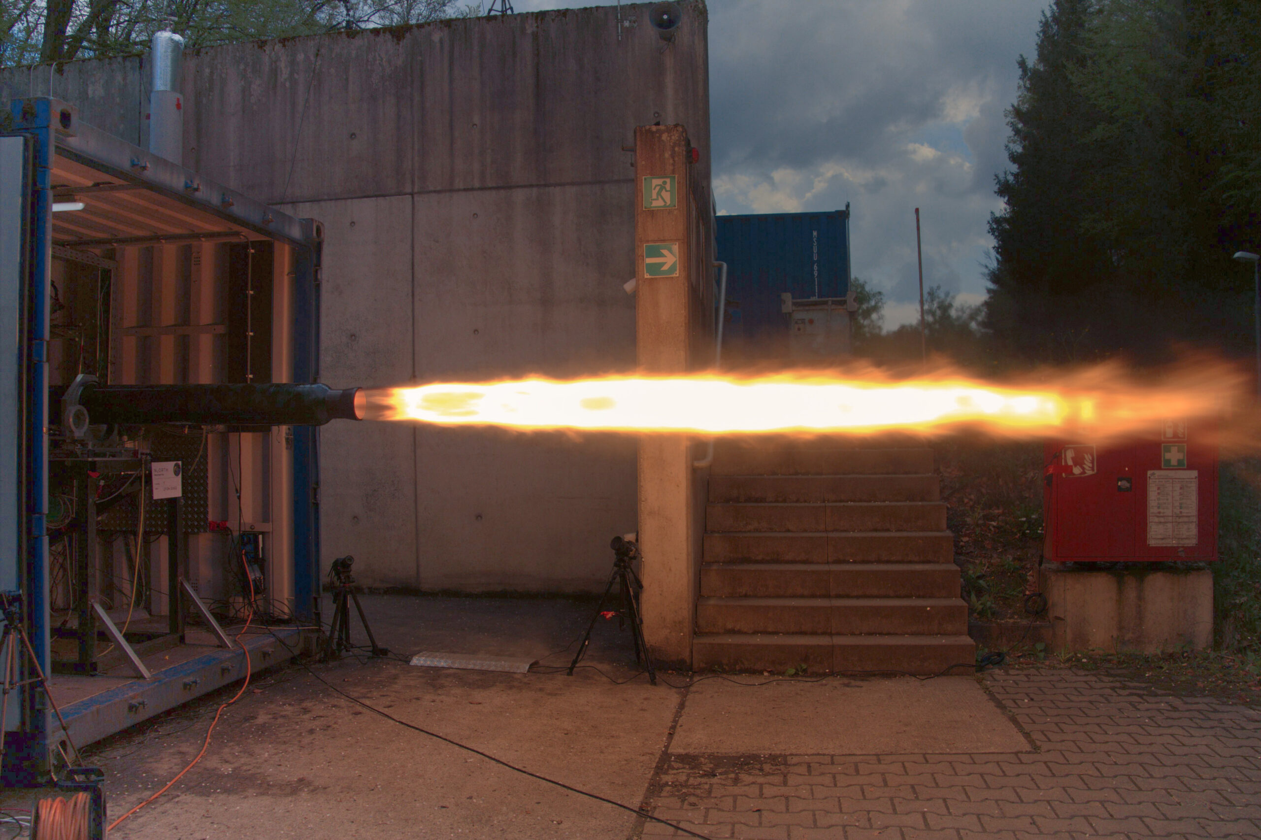
HyLIGHT engine on test bench.
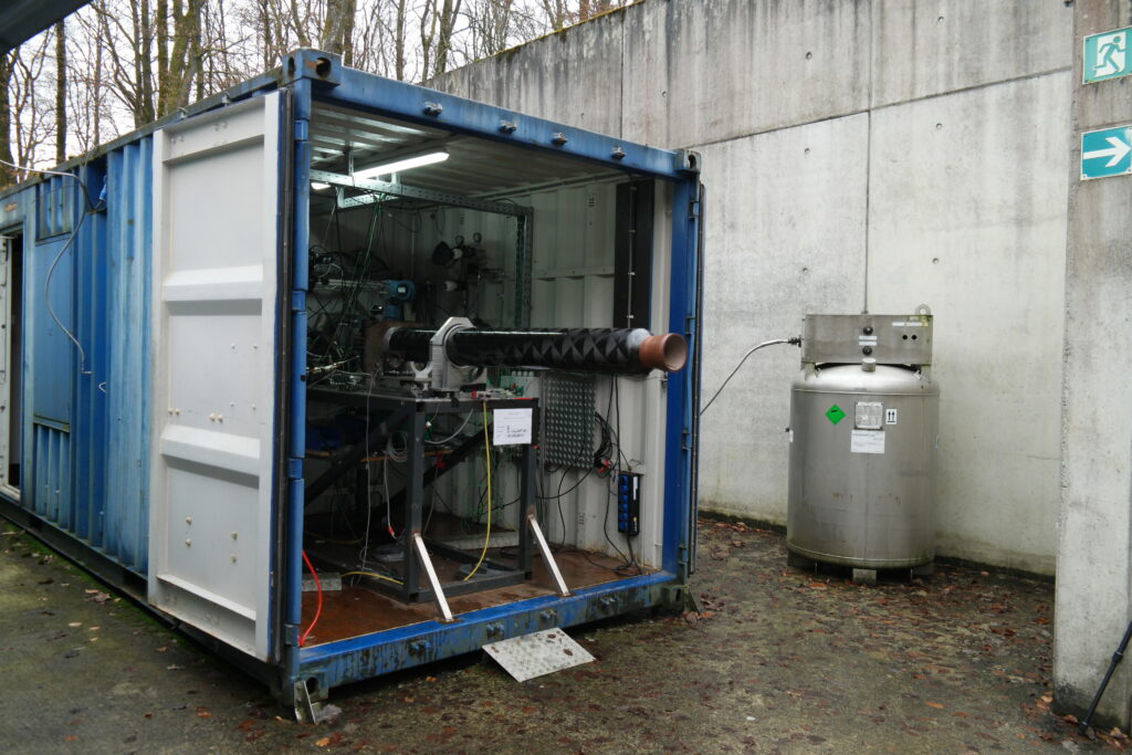
Testing our Engines
All tests are conducted at the DLR Institute of Space Propulsion Lampoldshausen at Test Bench M11.5. Most hot fires are conducted with constant tank pressurization using nitrogen. Additionally, blow down operation is tested together with other rocket systems (tank, valves, GSE) in a separate test before the launch.
Since September 2020, HyEnD has conducted more than 40 tests with the smaller HyFIVE rocket engine. Tests included the evaluation of the fuel regression rate and combustion behaviour as well as the test of different ablative insulation materials, injectors and mixing elements in the post combustion chamber.
HyFIVE Hotfire in Sept. 2020.
Test of ablative composite materials.
HyFIVE test preparations.
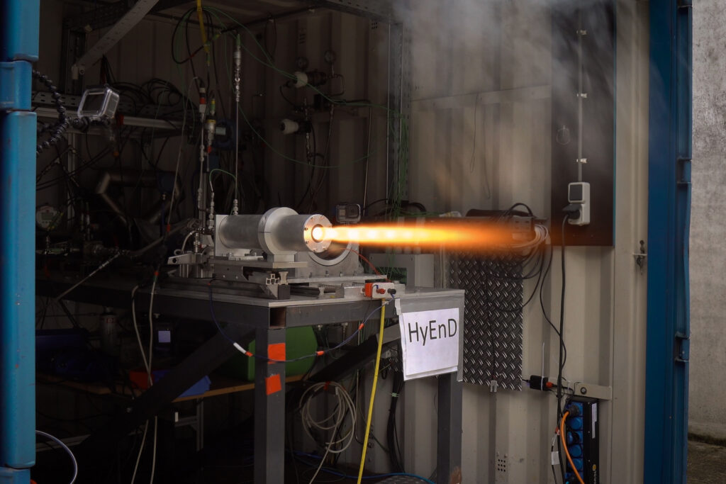
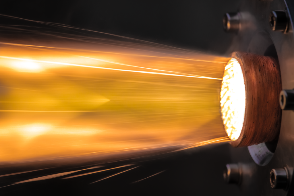
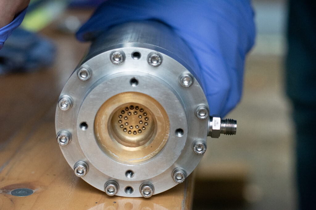
First tests with a modular HyLIGHT engine with an aluminum casing were conducted in September 2021. Smooth and efficient combustion was achieved by using a multi-element swirl injector in combination with a mixing element. Different fuel grain geometries and film cooling ablator materials were compared. First tests with the CFRP casing were conducted in early 2022. A total impulse of more than 267 kNs was tested in a single hot fire.
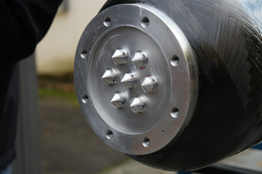
HyLIGHT swirl injector

View of nozzle

Engine in blow down operation
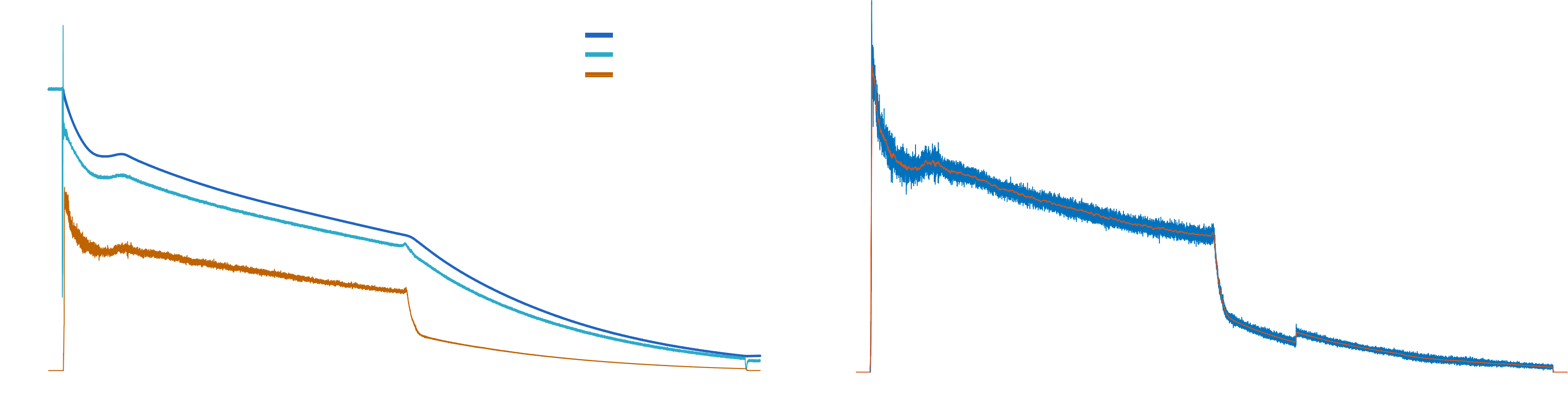
The final propulsion system test was conducted on December 8th, 2022. With a peak thrust of more than 15 kN and a total impulse of 255 kNs at sea level, we are confident that the propulsion system is capable of pushing N2ORTH to the frontier of space. The in-flight impulse of this configuration will be even higher since effects like flow separation will occur later in the operation time due to lower ambient pressure at higher altitudes. Moreover, the test showed good accordance to the simulation carried out in advance. This is especially important to ensure a safe flight trajectory of the rocket.
Structure, Oxidizer Tank & Aerodynamics
N2ORTH is built entirely out of composites to achieve the highest flight performance. All aspects of the structure have been optimized for weight and drag reduction. The components are fully manufactured in-house, except for the tank filament winding. To withstand shock heating during flight, all wetted parts are laminated with in-house developed high-temperature epoxy systems. Additionally, a thermal protection system has been developed for the entire rocket.
Nose Cone
To achieve RF-Transparency, the nose cone is manufactured of out glass fiber composite. The contour follows the LV-HAACK series to minimize drag. To protect from shock heating, the nose cone uses a phenolic resin and aramid honeycomb isolation.
Airframe
The airframe is filament wound in house from HT carbon fiber using an optimized pattern for bending and buckling resistance. It is protected by aerospace grade cork insulation and houses the engine, fluid and recovery system.
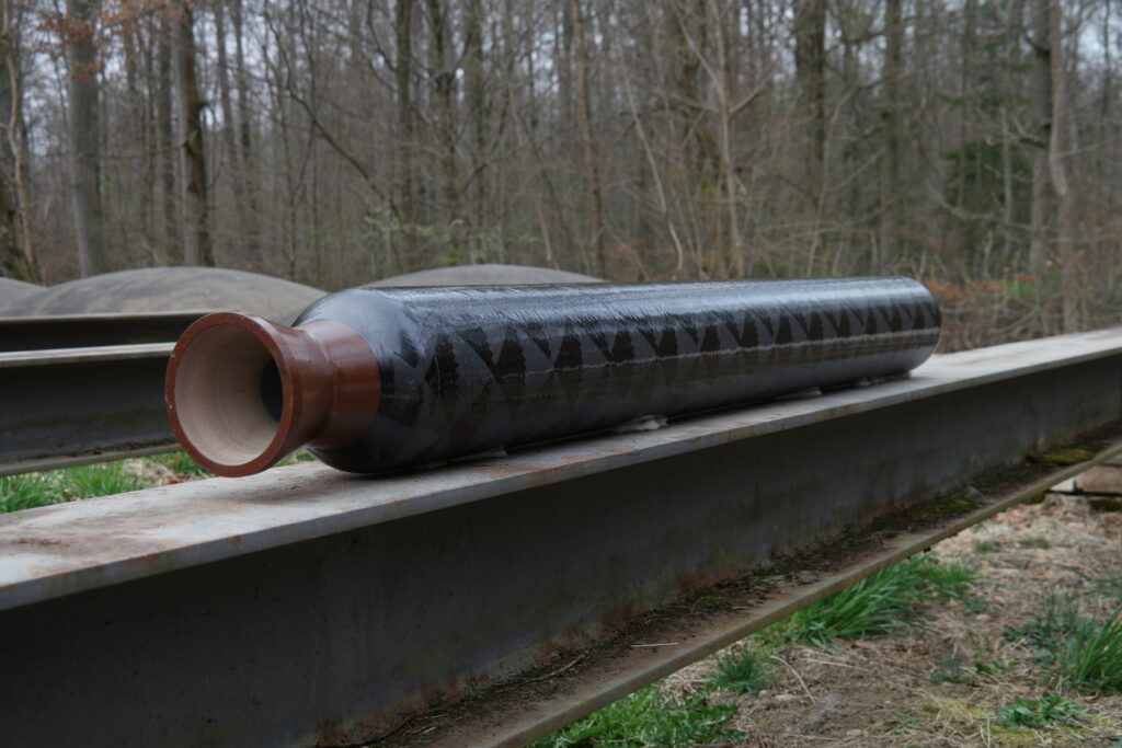
Oxidizer Tank
The rocket tank is a structural Type V composite pressure vessel, meaning that it uses no structural liner and no additional hull section. To withstand pressure and structural loads, the tank is filament wound from HT carbon fiber at one of our partners using a self-developed, load optimized pattern. Since epoxy matrix materials are not compatible with out oxidizer, a thin flouroether polymer film coating is used inside the tank.
Fins
The fins use a high strength carbon fiber sandwich construction to minimize weight, while their shape minimizes drag at the required stability for passive flight.
Epoxy Systems
All composite matrix materials used in the NORTH rocket have been self-developed leading to superior thermal and structural performance when compared to commercially available solutions. Additionally, no toxic or carcinogenic chemicals are used, dramatically improving safety during manufacturing.
Thermal System
All wetted components have been thermally verified using high fidelity CFD Data coupled with a thermal FEM simulation. This allows the optimization of thermal protection materials for minimum weight at the required performance.

Fluid System
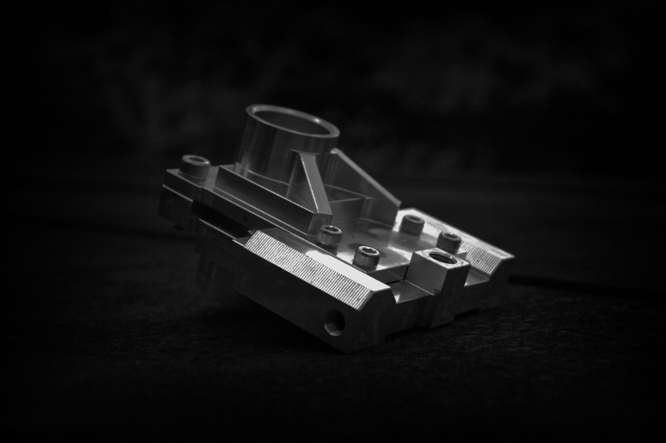
The fluid system is tasked with providing all necessary valves and interfaces to launch and fuel the N2ORTH rocket. The three main design drivers are weight, compactness and minimizing total pressure loss of the flow. The main and release valves were developed in-house. For the quick disconnect, the check valve and the relief valve, adequate commercial off-the-shelf components are available.
The demonstrator rocket Compass focused on proving the functionality of the system on a smaller scale by using the same working principles and design philosophies as the final flight components. The N2ORTH fluid system is optimized even further, incorporating the valve interfaces directly into the tank dome to reduce the number of components and save weight. An overview of the fluid system can be found below:
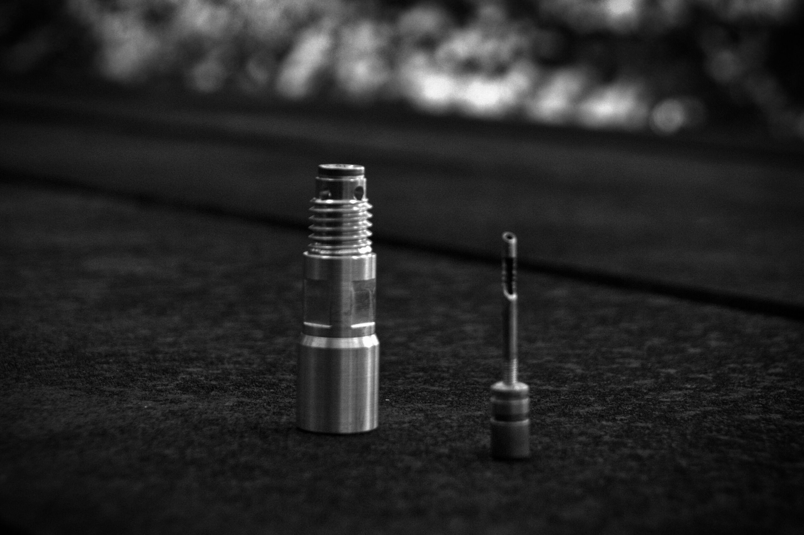
Main Valve
The development of the main valve is a substantial task of the fluid system. A pyrotechnically actuated design is chosen, where two pistons push a slider to open the valve. This allows for a complete separation of the pyro charge and oxidizer. The design and verification process started with a first subscale prototype and ended with the final flight version of N2ORTH main valve. An extensive test campaign was conducted to prove the reliability and safety of the valve. First actuation and pressure tests verified the concept at different temperature and pressure ranges. Multiple sets of pyrotechnic tests followed to determine a reliable operating window. A total of over 100 tests have been conducted to ensure a safe flight of the N2ORTH rocket.
Release Valve
For the release valve, a lightweight and reliable concept is developed, where a pyrotechnic charge pushes a nail through a membrane, allowing the oxidizer inside the tank to escape. The test campaign included actuation tests, pressure tests, as well as icing tests, to guarantee, that the rocket can be brought back into a safe state should anything go wrong during countdown.
Testing
The complete system was successfully tested on a subscale level during the Compass launch and the Compass static hot fire test. In addition, a full-scale blow-down test showed functionality of the final flight designs, paving the road for the launch of the N2ORTH rocket.
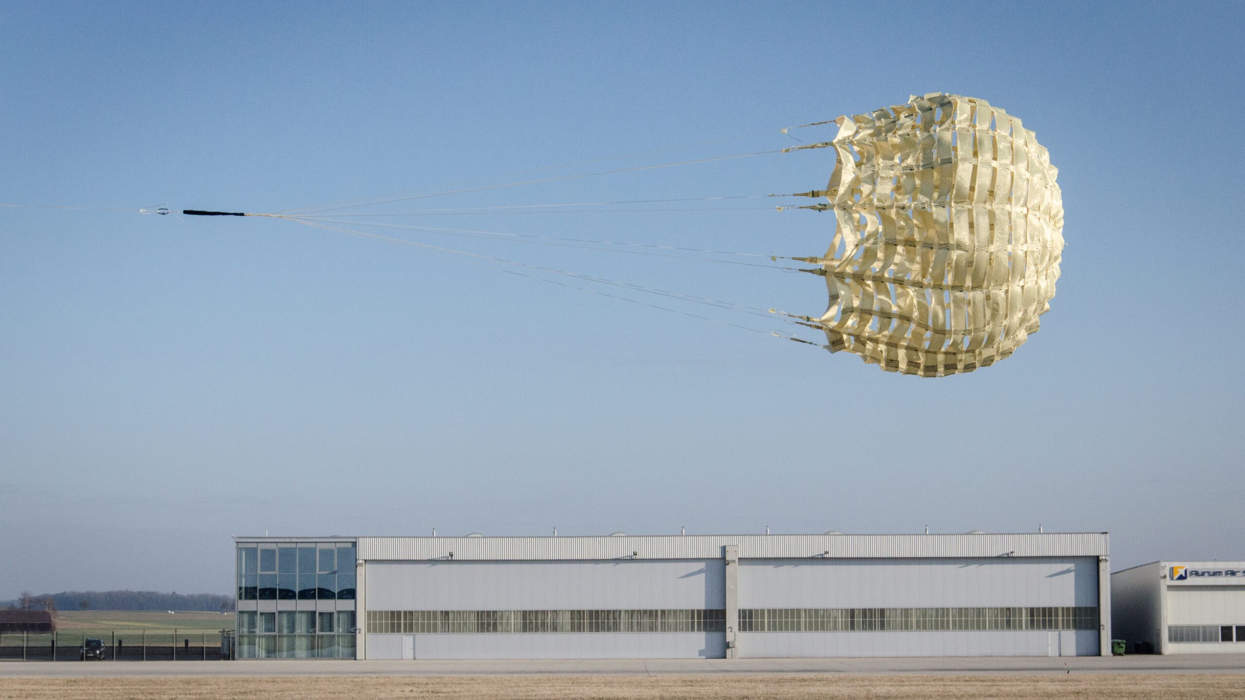
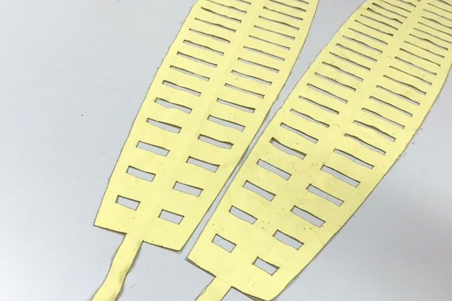
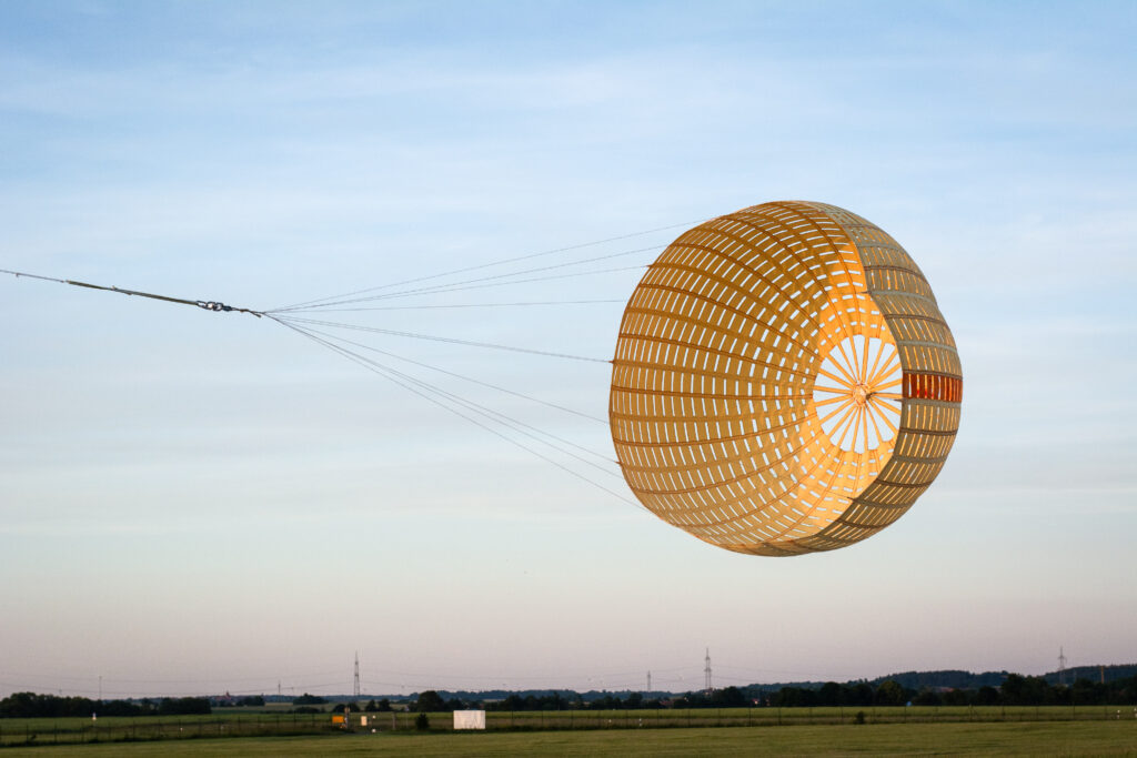
Recovery System
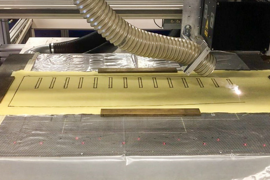
The N2ORTH recovery system is designed to perform the required safe landing of the entire rocket in a designated landing zone. It is divided into two stages: The drogue and the main stage. The drogue parachute is ejected at apogee to slow down the rocket to a steady descent rate. Due to the expected speeds, a supersonic drogue parachute becomes necessary. The self-developed construction features a hemisflo ribbon design and consists out of 18 aramid fabric segments shaping the chute’s canopy.
At an altitude of 3000 m, the second stage of the recovery system is triggered to further decelerate the rocket. All opening occurring shock loads are neutralized by a shock absorber.
The entire recovery bay is located in the upper part of the rocket. The following picture shows a schematic of the structure and the lines.
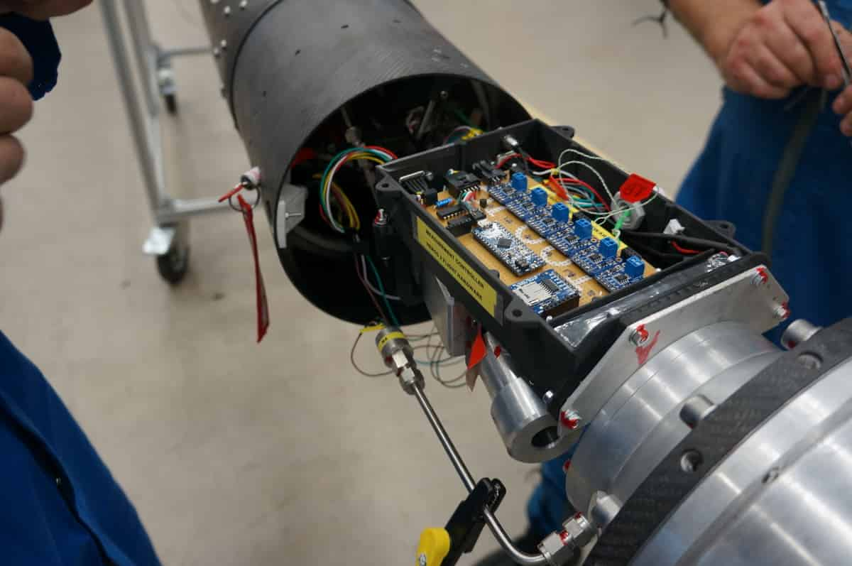
Avionics
The avionics need to fulfil multiple tasks, mainly activating the pyro lines firing the recovery system as well as collecting as much data as possible to allow further analysis after the flight.
It consists of many different modules, each one dedicated to a specific task e.g. gathering trajectory data. The systems can communicate between each other to allow the different modules to send their measurement data to a central microcontroller. The collected data will then be transmitted to the ground station.
In order to obtain pressure data of the engine and tank with a high sample rate, a custom module is designed to read and store the measurements with a sample rate of up to 10 kHz. This enables a detailed frequency analysis after the flight, making it easier to compare the behavior of the rocket in flight with the previous tests and simulations.
Another part of the avionics is dedicated to the powertrain. A stable and redundant power supply is extremely important. A loss of electricity will render the whole mission unsuccessful. The power train is customly designed to prevent a variety of common problems, like overvoltage and overcurrent as well as being able to switch between two sets of batteries and voltage regulators.
The parachute deployment is done via two parallel Telemegas. They will detect the apogee and trigger the recovery mechanism. Both will send additional data regarding the trajectory.
Ground Support Equipment
The ground support team is tasked with getting the N2ORTH rocket safely off the ground. This includes designing and manufacturing a launch rail, fueling system and ignition circuitry.
Launch Structure
The launch structure plays a substantial role in the success of the launch. It needs to support the fully fueled rocket and guide it during the first few moments of ascent. The alignment of all segments plays a crucial role in the accuracy of the calculated trajectory.
The rail system and fueling arm, consisting of carefully aligned truss segments with a supporting structure made from aluminum extrusions is mounted to the MRL rail in Esrange. It was successfully tested during the launch of Compass in a free-standing version with a shorter rail.
Fueling System
The fueling system must fill the rocket tank with liquid nitrous oxide and helium. It needs to be remotely controlled and has to be precise since the oxidizer quantity, pressure and temperature heavily influence engine performance and burn time.
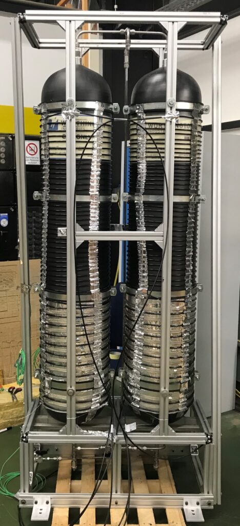
To control all parameters of the nitrous oxide, big intermediate tanks are used. These tanks are filled from gas bottles a day before the launch and can heat its content to the appropriate temperature. From there, the rocket tank is filled by pushing the nitrous oxide over using nitrogen pressure.
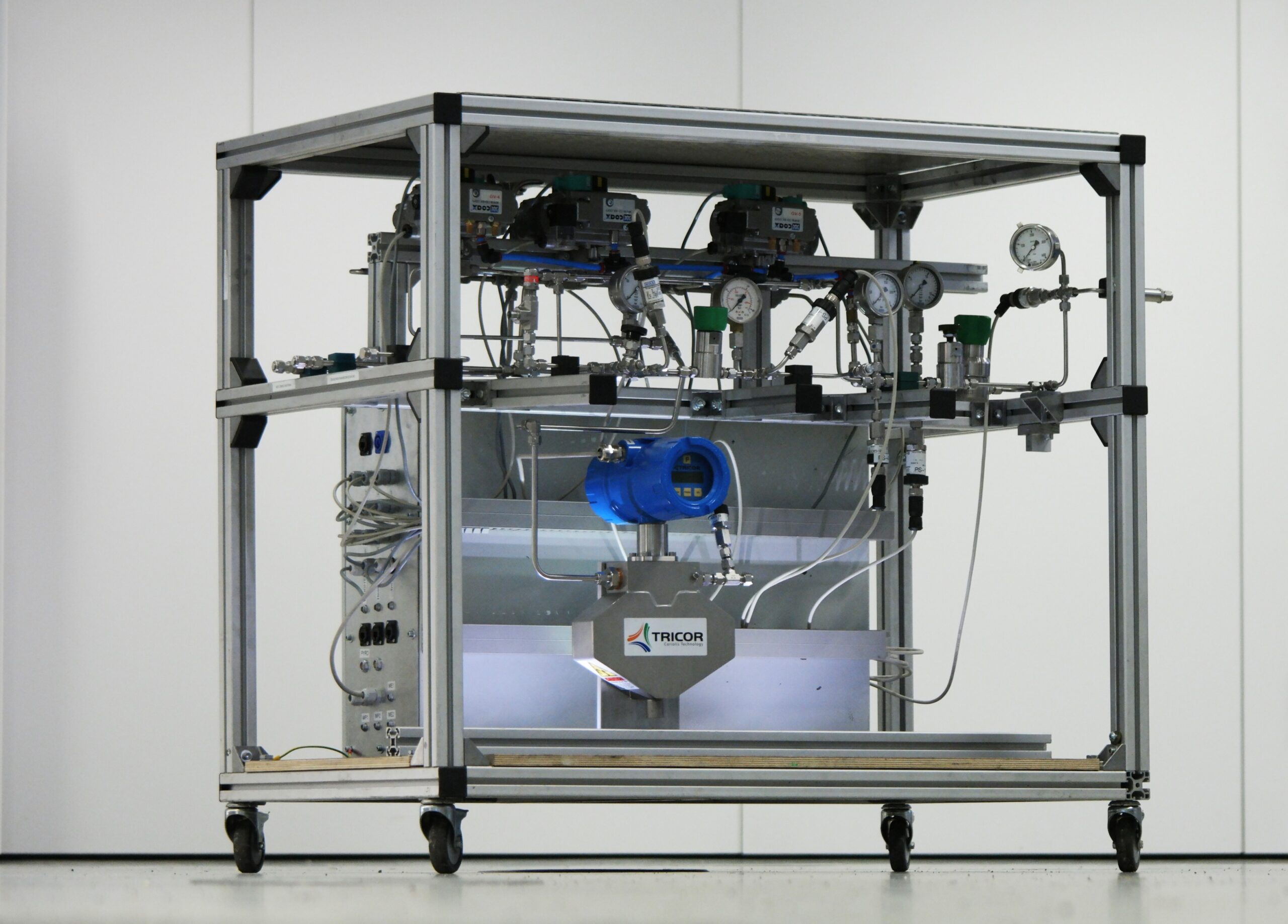
The precise remote control is achieved using the fueling cart. It contains pneumatic valves, pressure regulators, sensors and most importantly, a coriolis mass flow meter. This combination of sensors and actuators ensures high precision during the fueling process and full control over all parameters.
The electrical enclosure contains the fully custom electronics to control the entire launch process. They are based around a Raspberry Pi controlling STM32 based daughter boards over a CAN Bus. This provides great performance verified in multiple tests. Remote control is achieved with a GUI connected via Ethernet.
About the DLR STERN Program
The STERN (STudentische ExperimentalRaketeN) program of the DLR (German Aerospace Center) is a program which gives student groups from German universities the possibility to participate in a real space project. Student groups have the mission to develop an own rocket within three years, which shall reach at least 3km altitude and the speed of sound. All rockets are launched from the Esrange Launch Site near Kiruna, Sweden.
STERN finances the student projects with funds from the BMWi (Federal Ministry of Economics and Energy). During the STERN program, several German student groups participated with solid, liquid and hybrid rockets which were successfully launched from ESRANGE. During the program, each team is controlled and supported by reviewers from industry and DLR during the development of their rocket and undergoes the space-typical review process. The main goals of the STERN program are to train students on real space projects, gather teamwork experience (which is inevitable for space projects) and give the students the possibility to develop new technologies and inventions.
The Team
🚀 Launch Crew Members
🎓 Alumni

Maximilian Oechsle
Team Leader 🚀Project Management, Tank Development

Philipp Jochum
Chief System Engineering 🚀Propulsion Engineer, Tank Development

Colin Barth
Chief Structure & Aerodynamics 🚀Structure Engineer, Trajectory Simulations

Julian Dobusch
Chief Propulsion 🚀Propulsion Simulation, Test Campaigns

Marc Hazenbiler
Chief Fluid System 🚀Rocket Assembly

Robert Rödinger
Chief Fluid System 🚀Rocket Assembly

Florian Merz 🎓
Chief Recovery🚀
Martin Beer
Chief Recovery 🚀
Marc Gritzka
Chief Avionics 🚀Propulsion & Test Bench Engineer

Maximilian Stief
Chief GSE 🚀Software Development, Launch Procedure

Indira Keserovic
Structure & Aerodynamics Engineer 🚀Rocket Assembly

Alexander Schlitzer
Propulsion Engineer 🚀Injector Design, Logistics

Berthold Stegemann
Propulsion Engineer 🚀Lead Manufacturing, Public Relations

Bayram Stucke 🎓
Avionics Engineer 🚀Software Development

Julius Scherer🎓
Avionics Engineer 🚀Avionics Assembly

Matthias Roß
GSE Engineer 🚀GSE Electronics

Bernabé Lorenzo Ávila
Structure & Aerodynamics EngineerOxidizer Tank, CFRP Manufacturing

Dominik Gentner
Structure & Aerodynamics Engineer
Johannes Schmid
Structure & Aerodynamics Engineer
Johannes Walz
Structure & Aerodynamics Engineer
Sophia Wolters 🎓
Structure & Aerodynamics Engineer
Sophie Förste 🎓
Structure & Aerodynamics Engineer
Luca Ingrillini
Propulsion Engineer
Marc Brodbeck
Propulsion Engineer
Kajetan Weinmann
Propulsion Engineer
Julian Reiber
Fluid System Engineer
Adrian Knauer
Fluid System Engineer
Lena Jansen
Fluid System Engineer
Manuel Zimmermann
Fluid System Engineer
Daniel Ebner
Recovery EngineerCAD

Amelie Katzke
Recovery Engineer
Sascha Binder
GSE Engineer
Ben Oker
GSE Engineer
Sarah Gelbing 🎓
GSE & Fluid System EngineerAre you interested in sponsoring a world-record holding rocketry team? Then take a look at our sponsor presentation!